


Next Level Radio Networks
DIY Repeater for prepared civilians extends the range of a radio network

“Make things as simple as possible but no simpler.” The famous quote is usually attributed to Einstein and is itself normally presented in a simplified form. Ironic, don’t you think?
The sentiment is ancient but it applies to radios. Radios are inherently complex. In this series of articles, I try to simplify radio networks as much as possible and no more.
For the interested reader, here is the actual quote. You can see why it is simplified in common usage.
"It can scarcely be denied that the supreme goal of all theory is to make the irreducible basic elements as simple and as few as possible without having to surrender the adequate representation of a single datum of experience.[i]"
Next Level Radios
The next level means the next level up in functionality from an FRS (Family Radio Service) network. In the article after this one, we’ll cover a Do It Yourself (DIY) meshtastic network which is another approach to extending the range of a radio network. Mesh radio networks function differently than repeater networks.
Do It Yourself GMRS Repeater
The point of a repeater network is to extend the range of a radio network. You put a radio (at least the antenna) high up so it can listen for transmissions and repeat what it hears. Having the radio antenna high up extends the horizon for the receiving and transmitting radio waves.
You can see and be seen further from the top of a tall building or from a mountain. It is the same with radios. You can also use a repeater network to relay a radio signal over an obstacle like a hilltop or mountain.
This article explains how to build a DIY GMRS repeater network. I will not be operating these radios as a repeater network other than a few very brief test transmissions. This DIY GMRS repeater network is a “proof of concept” network for a true emergency when you need a repeater network to preserve life, limb, safety, or property. I also checked my area for repeaters and did my brief testing in a rural area near where I live so that I would not interfere with any existing repeaters. Finally, I listened in on the repeater output channels just to be sure before I transmitted.
You can find a list of repeaters at https://www.mygmrs.com/repeaters. myGMRS.com is a good resource. I recommend joining myGMRS.com after you get your GMRS license.
Understand and comply with the regulations that apply to GMRS repeaters. The regulations are in place to prevent interference and to facilitate effective operations of radio networks. See the explanation at the end of this article.
Dessert First – DIY Repeater Network
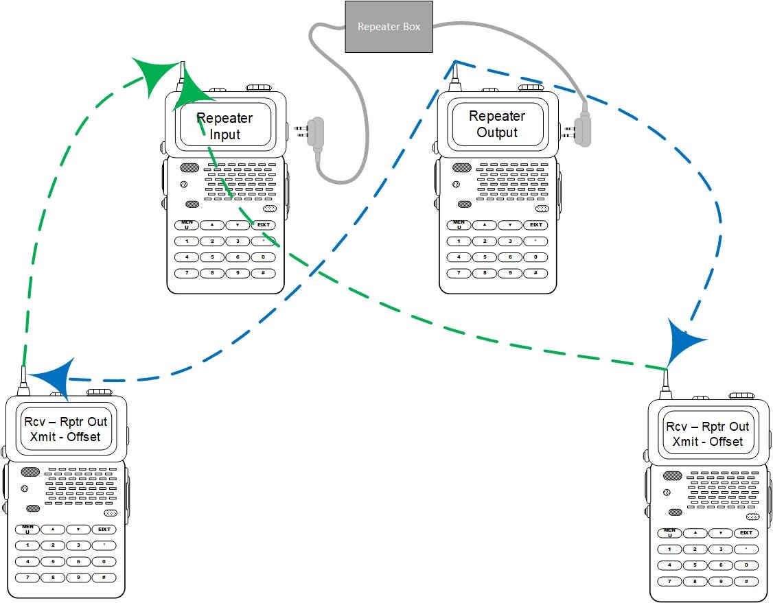
The picture at the top shows the diagram of my DIY (do it yourself) repeater network. To build a DIY repeater, you need two radios for the repeater pair and you need the other radios that you plan to communicate with. The diagram below shows the most basic DIY repeater network you can build. In real life, as you prepare for the SHTF environment, you will want to add better antennas and a power supply.
To build a DIY repeater, you need two programmable radios and a repeater cable to link the radios.
For my tabletop test, I used a repeater cable that I bought on Amazon (K-Head Repeater Box, RPT-2K Relay Walkie Talkie K-Head Two Way Radio Repeater Box for Baofeng UV-5R DM-5R GT-3TP Radio).
The cable connects the speaker of the repeater receiver to the microphone of the repeater transmitter. There is at least some minimal internal circuitry in the repeater cable box, but I could not find a schematic of the internal circuit. Apparently, even the internet doesn’t know what is inside the box.
When you look for a repeater cable, read the reviews. These are inexpensive devices and almost all of them are manufactured in China. Caveat emptor.
My “tabletop” test case didn’t work well with the stock antennas and the radios literally on a tabletop. There was considerable interference from the radios being so close to each other.
It worked perfectly when I set it up with external antennas that were separated by about twenty feet. I built simple dipoles (see further down in the article) and connected them to the radios with RG-58 cable.
For my test case, the only parameter I had to experiment with was VOX. It worked best for me to set VOX “OFF” on all the radios.
Commercial repeaters often use privacy codes. You may want to add privacy codes to your DIY repeater. I didn’t use any privacy codes for my table top test.
Repeater Antennas
Commercial repeaters use duplex antennas. The DIY approach shown here has two radios so you probably want to build two antennas and get them as far up into the air as you can. Separating the antennas as much as possible helps reduce interference. Each radio should have an antenna optimized for their frequency. Antennas are a science unto themselves and merit an article of their own but I include a brief primer further down in this article.
Offset Explained
By FCC Specification, GMRS radios use a repeater offset of 5 MHz. That means that your handheld radio transmits to the repeater on one of the repeater input frequencies and your handheld radio receives (listens) to the repeater on a frequency that is 5 MHz less than the transmit frequency. Your handheld radios must be programmable for that offset or have it programmed into them from the factory. If the repeater input frequency is 467.550 MHz (GMRS Repeater Input Channel 1) then the frequency (to listen to the repeater) is 462.550 MHz (GMRS/FRS Channel 15).
The repeater pair radios do not require this programming. Set the repeater input radio to the repeater input frequency and set the repeater output radio to the repeater output frequency.
For my inexpensive test radios, the offset is specified FROM the receiving frequency. That means I set the frequency to the receive frequency (channel 15 in the example above) and input an offset of “positive” 5.000 MHz. Then my radio listens on 462.550 MHz and transmits on 467.550 MHz.
Check your radio documentation to see how to program offsets for your equipment. Expect the documentation to be a little sparse and challenging.
The same principles would apply if you built a cross-band repeater. The input frequencies and offsets would change, but the principles are the same.
GMRS Radio Overview
A General Mobile Radio Service (GMRS) radio is an FM (Frequency Modulation) UHF (Ultra-High Frequency) radio that uses channels around 462 MHz and 467 MHz. The “channels” are frequencies assigned to GMRS by the FCC (Federal Communications Commission).
Frequencies are allocated or assigned by the FCC to avoid conflict between the various uses of radio networks. Cell phones have assigned frequencies. Airports and aircraft talk on their assigned frequencies. Using the assigned frequencies avoids interference.
GMRS is a licensed radio service. That means you need a GMRS license to legally transmit on the GMRS frequencies. You obtain a GMRS license online. A GMRS license costs thirty-five dollars and is issued for a ten-year term.
Acquiring a GMRS license is a two-step process. First, you acquire an FCC Registration Number (FRN) in the Universal Licensing System (ULS). Go to this site ( https://apps.fcc.gov/cores/userLogin.do ) to acquire an FRN.
After you have your FRN, you apply for your GMRS license starting with this site ( https://wireless2.fcc.gov/UlsEntry/licManager/login.jsp ). Enter your FRN and FRN Password, then find the “Apply for a New License” link on the “My Licenses” page.
It should only take a day or two for your application to be approved. You will get an approval email with a link to download and print your “Radio Station Authorization.” This license document will have your GMRS call sign. My call sign is WSAU756.
Call sign usage is required when operating a GMRS radio. If you transmit a single message, then you append your call sign to the end of the message. If you are sending and receiving multiple messages (a conversation) then you must transmit your callsign no less than once every 15 minutes.
FRS and MURS
FRS (see the last article) and the Multi-Use Radio Service are “licensed by rule.” That means an individual license is not required to operate an FRS or MRS transmitter (radio) if you follow the FCC rules. MURS has five frequencies assigned to it. These frequencies are in what is sometimes called the two-meter band. The reason for the name is that the wavelength of the MURS frequencies is about two meters. I’m not going to do anything with the MURS frequencies in this series of articles. The MURS frequencies are shown below.
151.820 MHz (11.25 kHz)
151.880 MHz (11.25 kHz)
151.940 MHz (11.25 kHz)
154.570 MHz (20.00 kHz)
154.600 MHz (20.00 kHz)
GMRS Radios – Just The Facts
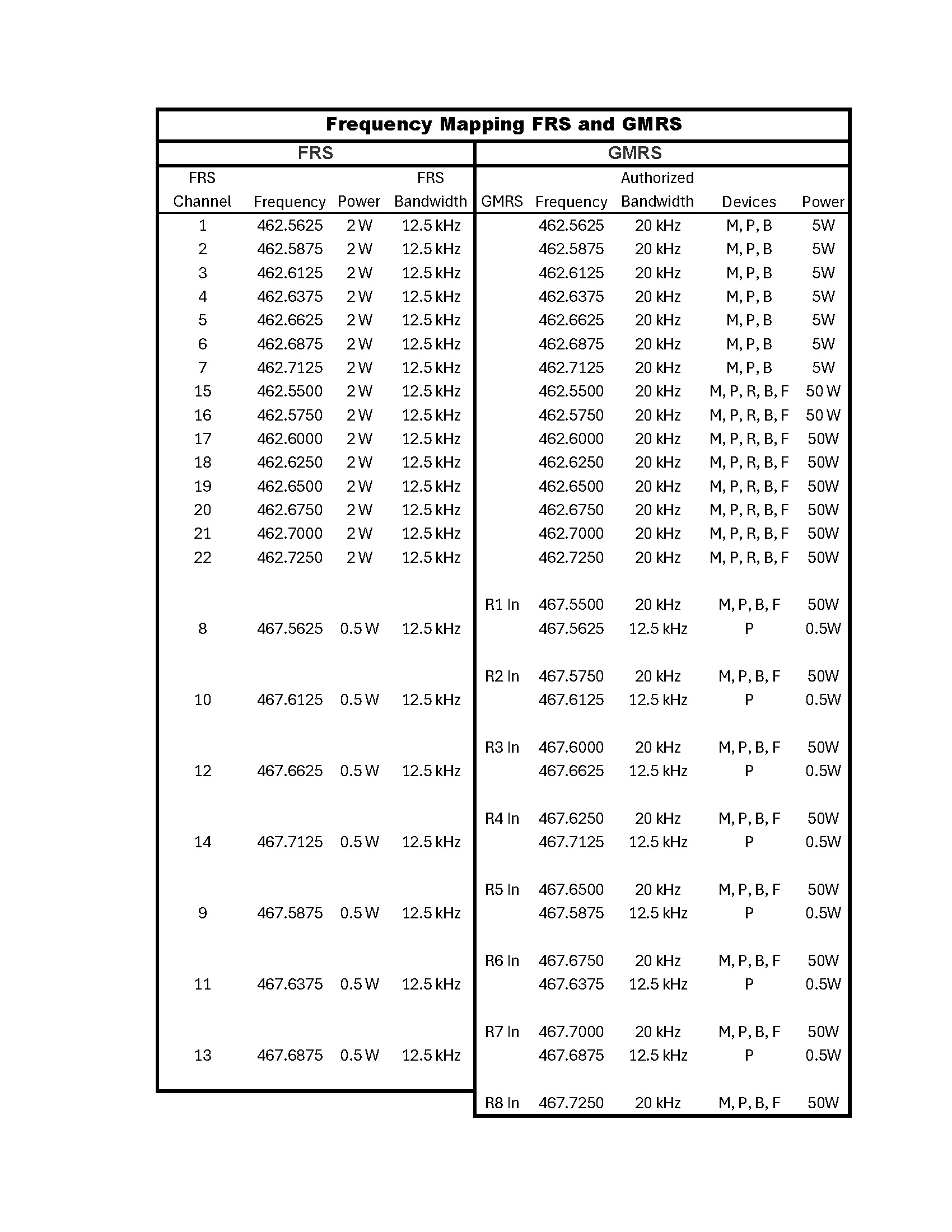
GMRS radios operate (transmit and receive) on thirty channels. These channels are shown in the table a little further down. I organized this table by frequency. The thirty GMRS channels (frequencies) are not reserved to any user nor organization and are available for all to use. Having said that, there are some differences in the devices permitted and the transmit power allowed on each channel.
To illustrate, only portable devices are allowed on the frequencies shared between GMRS and FRS for the seven FRS channels 8 through 14. This is the frequency range from 467.5625 MHz to 467.7125 (see the table). And transmitters are limited to ½ (0.5) watt of transmitted power on these channels.
A portable device is a handheld device. It might seem that a handheld radio is a mobile device but a mobile device is defined by the FCC as a transmitter that is designed to be used in “such a way that a separation distance of at least 20 centimeters is normally maintained between the transmitters radiating structures and the body of the user.”[1] Handheld radios are not separated from the user by 20 centimeters.
In the table below, the device column shows what devices are permitted on each frequency and the maximum transmitter power output.
“M” means a mobile device. That could be a vehicle mounted radio or a desktop radio that is movable from one location to another. “P” means portable which means hand-held radio. “R” means repeater. That is a radio that receives on one frequency and transmits the received message (repeats it) on a different frequency. “B” means a base station. That is a transmitter at a fixed location. “F” is for “Fixed” which is for communications between fixed points.
We are only going to work with portable (P) devices but it was worth a couple of paragraphs to cover the topic because of the channel restrictions. We are going to create a DIY repeater using portable devices.
GMRS Radio capabilities
The radios you can buy that are advertised as GMRS radios vary in capability. As an example, some GRMS radios can receive and transmit only on GRMRS channels that are programmed in by the manufacturer. Other radios sold as GMRS radios can also operate in other frequency bands. The fact that the radio is capable of those other frequency bands doesn’t, by itself, give you a legal capability to use those other bands. Understand the regulatory requirements before you transmit.
Caveat Emptor
Not all radios work as you would expect. I bought a Radioddity radio which advertised itself as GMRS and it is as long as it is in “Channel Mode.” I switched the radio to frequency mode … and it wouldn’t transmit on the FRS channels nor the GMRS channels. A few minutes research online confirmed that this is how Radioddity intended the radio to work.
That’s fine if you only intend to use the radio on the GMRS channels. It is probably not fine for a radio network for prepared civilians.
Setting Up Your Radios
Configuring Radio Functions
Most GMRS radios have the following functions. Each radio manufacturer will have a different method for changing the function. Use your owner’s manual to figure out how to configure your radio. Do the radio configuration ahead of time. Expect the owner’s manual to be terse, maybe confusing, and probably frustrating.
Offset
Offset programming applies to the hand-held radios your team, family, or organization will use. Only buy radios that let you program the offset. The “offset” is the channel that a radio listens on when talking to a repeater.
To use an “offset,” you program a receive frequency and then specify an offset. The offset is either negative or positive. The radio then operates on two frequencies. It receives on the programmed frequency and applies the “offset” to derive a transmit frequency.
That is how my cheapo test radios work. Check your radio documentation to understand how your equipment works.
Keypad Lock
It is always a good idea to lock the keypad once you have completed setting your radio functions. Locking the keypad prevents inadvertently changing settings or unintentionally triggering events with the radio.
Silent Operation
For almost all radio networks, silent operation is preferred. Beeps and chirps always seem to occur when silence is really important. In general, you should set up your radios ahead of time and operate them silently when “in the net.” Silent means the radio doesn’t make noises and it only transmits when you want it to transmit.
Call Alert
Call alerts are useful in noisy environments. In any sort of prepared radio network environment, call alerts should be turned off. That includes vibration alerts as well as audible alerts. Vibration alerts can often be heard at a greater distance than you think. Making the radio vibrate emits an electronic signal. That electronic signal is more detectable than you might think.
VOX
VOX means voice operated. It should be disabled (turned off) for most networks. VOX means that the radio listens and when you speak, it transmits. For almost all “prepared civilian” radio networks, VOX should be disabled. An exception may be when building a DIY repeater. Depending on the repeater cable you use, VOX may be required. Different repeater cables work differently. A heuristic approach is required.
Privacy Codes
Privacy codes are not actually private. Privacy codes prevent you from hearing other radios but they do not prevent other radios from hearing you. Privacy codes should be disabled under most circumstances.
Privacy codes may be useful when building DIY repeaters to avoid having folks outside your network trigger your repeater. More on this in the repeater section below.
There are two types of privacy codes (CTSS and DCS). CTSS means Continuous Tone-Coded Squelch System. When you enable CTSS, the radio transmits a tone at the beginning of the transmission that is too low in frequency for the human ear to hear. FRS radios use these tones to do a sort of call screening. CTSS is analog. DCS (Digital Coded Squelch) is a digital method for accomplishing the same call screening.
The key point here is that a radio with CTSS and DCS disabled hears all transmissions. CTSS and DCS don’t give you any privacy from radios listening to the network. When you turn off CTSS and DCS, you hear all transmissions including those that include a “privacy” code.
If you use privacy codes, all the radios in your network should be set to the same privacy codes. Then you’ll only hear your network radios. Other radios outside your network with privacy codes disabled can hear your radios.
Power Selection
Most radios may have a high power and a low power setting. Low power should be the default and you should use high power only when you need it for longer range communications. Batteries last longer on low power. You interfere less with other radio users on low power. And, if it’s important, you are stealthier on low power.
Roger Beep
If your radios have a “Roger Beep” function, disable it. Roger Beep sends a beep at the end of your transmission. Learn to use the pro word “Over” and turn off the “Roger Beep.” Pro words should be part of your predefined communications protocols.
Frequency Chart (FRS, GMRS, MURS)
Is there anything more boring than a chart like the one shown below? Even though it is eye-glazing to look at, it’s worth a few minutes of study and it is a good reference. As you study it, pay particular attention to the devices allowed on each channel and the power limits for each channel.
I organized this chart in ascending frequency order. As you build a radio network for whatever contingency you are preparing for, frequencies will be more important than channel designations.
Frequencies, Wavelengths, and Antennas
An effective repeater network will almost certainly require external antennas. A brief primer on frequencies and wavelengths will help in understanding antennas and how to build them.
Radio signals are electro-magnetic waves that travel through space. Space includes our atmosphere. Radio waves oscillate or go “up and down.” Waves on water is a useful visual analogy for radio waves though the two phenomena are different. One key difference is that radio waves travel at the speed of light. The speed of light[ii] is 299,792,458 meters per second in a vacuum. Earth’s atmosphere is not a vacuum but that speed is close enough for our antenna work below.
Radio waves have a length analogous to the length of waves in water. The length of the radio wave is measured from one peak to the next. If you look at waves of water coming into a shoreline, you can see the distance between the top (peak) of one wave to the peak of the next wave. Radio waves coming into a receiving antenna also have a distance from one peak to the next. A wave peak arrives and then, after an interval, another peak arrives.
The number of peaks or waves in each interval is the frequency. Ocean wave frequencies range from zero (a flat ocean) to a few waves per minute.
Radio waves range from hundreds of wave peaks every second to billions of wave peaks every second. If you could directly observe radio waves (you can’t), you would see a wave peak passing by hundreds of times per second or billions of times per second. The number of wave peaks that pass by in a second is measured in a unit called “hertz.”[iii]
A frequency of thousands of wave peaks per second is called “kilohertz” and is written as kHz. A frequency of millions of wave peaks per second is called “megahertz” and is written as MHz. Billions of wave peaks per second are called “gigahertz” and are written as GHz. There are frequencies above (faster than) GHz but that is a different topic for interested readers.
We can use the frequency and the speed of light to determine the wavelength. The formula is:
Wavelength in meters = Speed of Light / Frequency in Hertz
GMRS Wavelength Calculation
GMRS Channel 1 Wavelength = Speed of Light / Channel 1 Frequency
0.6481 Meters = 299,792,458 / 462,562,500
0.6481 Meters is about 25.54 inches.
MURS radio wavelengths can be calculated in the same way. MURS wavelengths are about 2 meters. You may hear the MURS band of frequencies referred to as the “Two Meter Band.”
The wavelength has practical implications. Longer wavelengths can be heard by radio receivers at greater distances. The distance differences can be very significant. GMRS practical radio distances range from a mile or less to a few miles.
Two-meter radio distances can be much greater. Two-meter radios can transmit several tens of miles and much more in optimum conditions.
Radios that operate in the lower frequencies (down in the 3 to 30 MHz bands) can go much further. The radio waves there are long enough that they will “bounce” off the ionosphere and “skip” for long distances. On one of my trips to Kenya with the Army, we established voice radio communications from Kenya to Ohio using a 30-watt radio with a 1,000 (one thousand) foot long wire antenna. The “communications window” was only open for about an hour each night but during that hour we could talk voice from Kenya to Ohio with a 30-watt transmitter.
Longer wavelengths can be heard at greater distances. Is that good? It depends. If you’re trying to communicate as far as possible, it’s good. If you don’t want your signal heard at a distance, it’s bad.
External Antennas
An effective way to extend the range of a GMRS radio (including a repeater) is to use an external antenna. External antennas can be raised on a mast which extends the line-of-sight range. You can see further from the top of a building than you can from the ground. Radios work the same way. A radio with a tall antenna can transmit and receive at greater distances than a radio with a ground level antenna.
External antennas can also be “tuned” to be more effective transmitters. The effectiveness of an antenna is measured by something called the Standing Wave Ratio or SWR. SWR is a measurement of how well the antenna matches the radio. If the antenna is not well matched to the radio[iv], then some of the radio energy is reflected back into the radio. If the antenna is well matched, then all (or at least most) of the transmission power of the radio is radiated from the antenna.
For prepared civilian purposes, antenna tuning comes down to antenna type, antenna shape, and working with the length of the transmitting elements. Very small variations in shape and length can make big differences in antenna effectiveness.
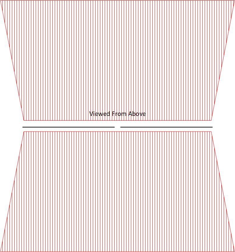
For most uses, a prepared civilian can get by with one of two external antenna types. A dipole is a ½ wavelength antenna with two radiating elements. Dipoles can be oriented vertically or horizontally.
As viewed from above, a horizontally oriented dipole has a somewhat bi-directional radiation pattern (shown below). It radiates less off the ends. It radiates upwards as well as outward in two directions.
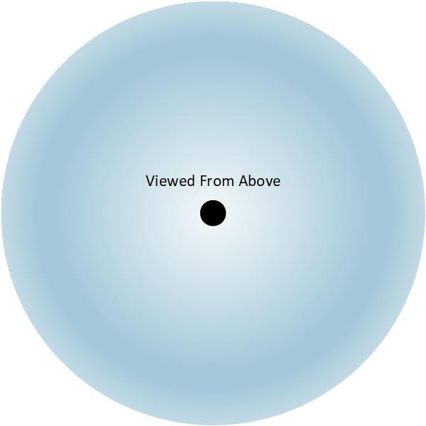
A vertically oriented dipole has a radiation pattern like that below. Again, this is viewed from above. The antenna is the dot in the middle and the blue is the radiation pattern.
Orient your dipole horizontally when you need more signal strength in a particular direction. Remember that it has a “back blast” as well. That matters if stealth matters.
If a dipole isn’t sufficient, then a “jungle antenna” will probably work. A jungle antenna has the same radiation pattern as a vertically oriented dipole.
Directional antennas are easy to build as well. Long wire antennas, sloping “V” antennas, Yagi antennas and others are simple to build. I’ll likely cover those in a future article.
The reason that these two antennas (dipole and jungle antenna) are probably sufficient is that most prepared civilian radio networks are basically local. That means that they are operating within a radius of a central point. The radius can be a mile or two or much further. The height of the antenna at the central point is a primary control factor for the operating radius. The communications radius increases as the antenna gets higher (higher means further off the ground).
Dipole Construction
Both antennas are simple to construct. Below is a picture of a dipole that I built for GMRS frequencies. After a bit of tuning, I achieved an SWR of 1.01 with this antenna.
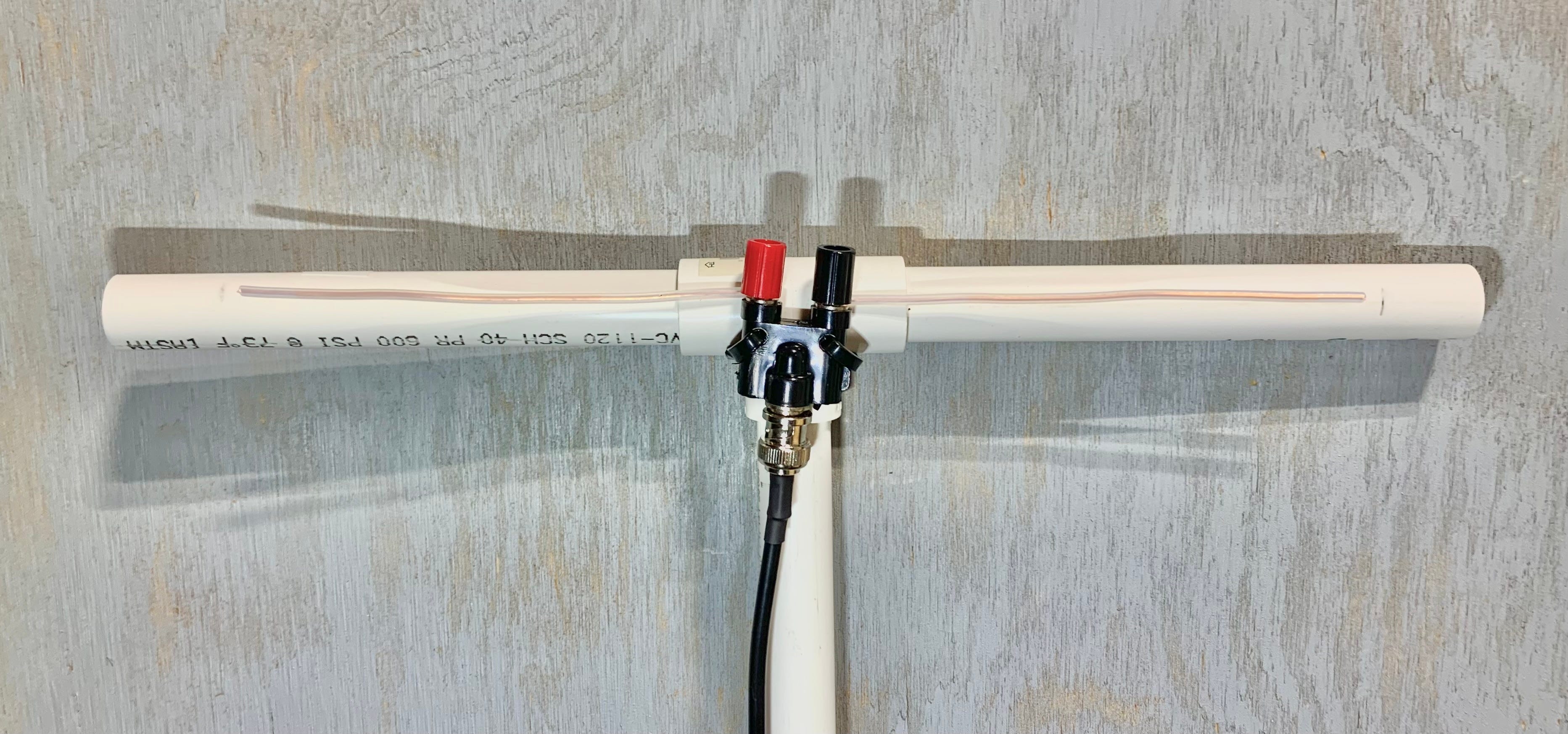
This antenna cost only a couple of dollars to build. You need a “cobra head” which costs about $3.50 ($7.00 for a two-pack) on Amazon. You’ll need coax cable with a BNC male connector. I used RG-58 cable. The cost of that depends on the length. You’ll need two radiating elements (wire) and you’ll need something to hold the antenna. I used a bit of scrap PVC as the antenna holder/protector. You’ll notice that I haven’t yet fastened my radiating elements to the horizontal PVC spars. I’m still figuring out what to use as spacers between the spar and the radiating element.
Dipoles are (slightly less than) ½ wavelength in total length. The radiating elements should start at ¼ wavelength. The practical formula for calculating ¼ wavelength is:
234 / Frequency in MHz = Radiating Element Length in Feet
For GMRS that is:
234 / 462.5 = 0.506 feet
or
234 / 467.5 = .0500 feet
In either case, you start with a six inch radiating element.
Then you start tuning. Tuning means shortening in most cases. In my case, the SWR started around 6. I shortened the elements in 1/16 inch increments until the SWR came down to 1.01. It is important that both elements be the EXACT same length. Small increments are the way to go.
I measured the SWR with an inexpensive SWR meter that I bought on Amazon. If you are serious about your radio network then you will be serious about your antennas. If you are serious about antennas then you need an SWR meter.
Jungle Antenna Construction
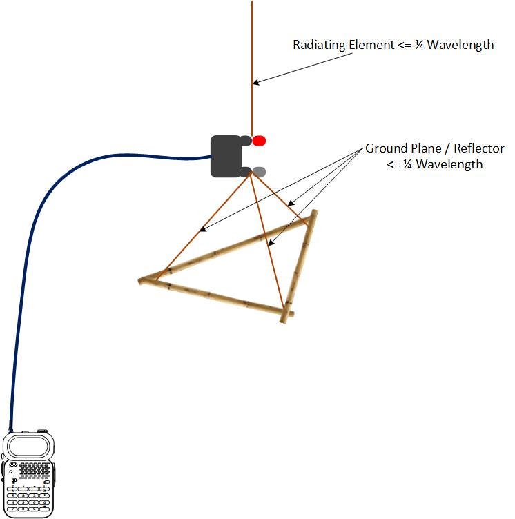
A jungle antenna has a ¼ wavelength vertical radiating element on top and it has a three-element “ground plane” or “reflector” on the bottom. The ground plane elements are ¼ wavelength as well. Jungle antennas get their name from radio operators building antennas and hanging them from the tops of trees in jungles. Getting the antenna up to the top of the tree gets the radiated signal above most of the jungle vegetation.
Disclaimer
The FCC regulates radios in minute detail. You can readily buy radios that you are not legally allowed to use. It is on you to understand and comply with the regulations that apply to your usage of the radios.
It is a little bit of a tricky dribble to create and test radio networks that comply with the regulations and provide the capabilities you will need when the SHTF (SHTF is an acronym for when the fecal material hits the rotating air dispersion device). When the SHTF, then “emergency use” provisions apply.
Getting a GMRS license is a good start on complying with the regulations. GMRS is more usable for “prepared” scenarios than FRS but a GRMS license is required to legally use a GMRS radio. GMRS licenses cost $35.00 and are available online. A GMRS license is valid for ten years.
[1] https://www.govinfo.gov/content/pkg/CFR-2011-title47-vol1/pdf/CFR-2011-title47-vol1-sec2-1091.pdf
[i] https://skeptics.stackexchange.com/questions/34599/did-albert-einstein-say-make-everything-as-simple-as-possible-but-not-simpler
[ii] https://en.wikipedia.org/wiki/Speed_of_light
[iii] https://en.wikipedia.org/wiki/Hertz
[iv] SWR is a complex and technical topic. For more information, see: https://en.wikipedia.org/wiki/Standing_wave_ratio